
Carbon Forks Versus Carbon Frames
"If titanium is a thougher mroe durable material than carbon fiber, why does Seven use carbon forks instead of titanium forks?"
It's a reasonable question. xxxxxxxxxxxx
First, why not titanium forks?
The quick answer is that titanium wants room to create stiffness larger diameter is stiffer. Fork crowns are compact and tight space. Everyone wants a shorter crown. this is illsuited for titatium.
3D printed titanium crowns might seem like a good solution. Nope. xxxxxxx
Second, why carbon xxxxxxx
If high quality carbon forks were as under-built and fragile as lightweight carbon frames, you'd probably never want ride them.
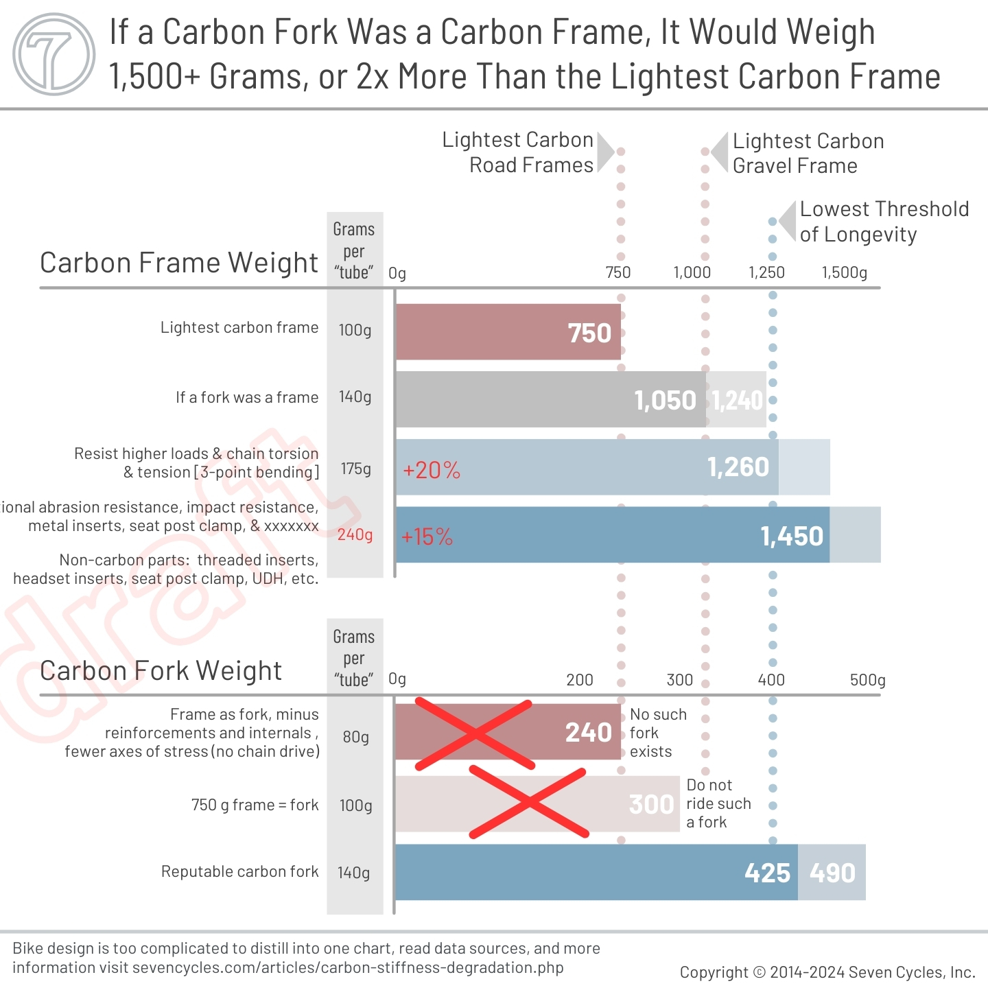
The disparity between carbon fork engineering and frame engineering is startling. The current generation carbon frames are significantly under-built relative to reputable and time-tested carbon forks.
Compare by weight: Well designed carbon road disc forks weigh about 425g. Carbon gravel forks weigh about 500 grams. A fork can be thought of as three tubes (each fork leg and the steerer). 425g ÷ 3 = ~140 grams per "tube." The lightest stock carbon frames are about 750 grams. Most frames have seven or eight "tubes." 750g ÷ 7.5 = ~100g per "tube."
We have to go through a few steps to reach a frame that's as durable as a carbon fork. First, as a baseline, a frame that uses a fork as it's template would start at about 1,050 grams (140g x 7.5). Next, a frame has to withstand significantly higher loads and deflections. Additionally, the chain drive complicates torsion and loading significantly xxxxxxxx. At best, this would add at least 17% to the tubes' weight. Then, we have to think about impact resistance and abrasion differently than a fork. This adds at least another 6% to the durable frame. Lastly, a frame has metal parts not needed in a fork, including threads for the bottom bracket, metal inserts for the headset, some kind of seat post clamping mechanism, and a few other bits. All told this adds about 100 grams or more to the frame. Add this together and the frame is about 1,400 grams; nearly double the weight.
1,050 x 1.17 = 1,230 x 1.06 = 1,300 + 100 = 1,400 grams.
A frame has to be stiffer than a fork. For example, the average fork blade stiffness is about 30% lower than the average chainstay-seatstay-dropout stiffness.Next, all performance carbon forks of any repute have 5-year warranties. Some carbon frame suppliers offer lifetime warranties. That doesn't make any sense.
Regarding warranties and safety, we strongly recommend replacing your carbon fork (of any brand) within that time frame. Having a fork fail while riding is one of the worst things that can happen. While Seven has never had one of our carbon forks fail from fatigue, it's not worth taking any chances.
Footnotes
- ∧ Specialized Bikes owner's manual.
- ∧ Cannondale owner's manual.
- ∧ Cervelo owner's manual.
- ∧ Vassilopoulos, A. P., editor, (2015). Fatigue and Fracture of Adhesively-bonded Composite Joints - Behaviour, Simulation and Modelling, page 450.
- ∧ Vassilopoulos, A. P., editor, (2015). Fatigue and Fracture of Adhesively-bonded Composite Joints - Behaviour, Simulation and Modelling, page 450.
- ∧ Morita, Naoki, et al., (2021) Versatile fatigue strength evaluation of unidirectional CFRP specimen based on micro-stress analysis of resin, Composite Structures Volume 276. Figures 3 & 5.
- ∧ Hirukawa, Hisashi, et al., (2022) NIMS fatigue data sheet on gigacycle fatigue properties of A6061-T6 (Al-1.0Mg-0.6Si) aluminium alloy at high stress ratios, Science and Technology of Advanced Materials: Methods Volume 2, Pages 232-249, Figure 3. [R=-1]
- ∧ xxxxxxxxxxxxxxxxxxxxxxxx
- ∧ (2011) Standard Test Method for Mode I Fatigue Delamination Growth Onset of Unidirectional Fiber-Reinforced Polymer Matrix Composites, ASTM International D6115 - 97.
- ∧ Martin, R., et al., (1988) Characterization of Mode I and Mode II delamination growth and thresholds in graphite/peek composites, NASA National Aeronautics and Space Administration.
- ∧ Thomson, Daniel, et al., (2024) Influence of fatigue damage on the impact performance of toughened-interleave carbon fibre epoxy composite laminates, Composite Structures Volume 345, page 3.
- ∧ Thomson, Daniel, et al., (2024) Influence of fatigue damage on the impact performance of toughened-interleave carbon fibre epoxy composite laminates, Composite Structures Volume 345, page 3.
- ∧ Thomson, Daniel, et al., (2024) Influence of fatigue damage on the impact performance of toughened-interleave carbon fibre epoxy composite laminates, Composite Structures Volume 345, page 3.
- ∧ Thomson, Daniel, et al., (2024) Influence of fatigue damage on the impact performance of toughened-interleave carbon fibre epoxy composite laminates, Composite Structures Volume 345, page 3.
- ∧ Thomson, Daniel, et al., (2024) Influence of fatigue damage on the impact performance of toughened-interleave carbon fibre epoxy composite laminates, Composite Structures Volume 345, page 3.
- ∧ Blythe, Ashley, et al., (2022) Stiffness Degradation under Cyclic Loading Using Three-Point Bending of Hybridised Carbon/Glass Fibres with a Polyamide 6,6 Nanofibre Interlayer, Journal of Composites Science 6(9) 270.
- ∧ Blythe, Ashley, et al., (2022) Stiffness Degradation under Cyclic Loading Using Three-Point Bending of Hybridised Carbon/Glass Fibres with a Polyamide 6,6 Nanofibre Interlayer, Journal of Composites Science 6(9) 270.
- ∧ Feng, Zihao, et al. (2023) A Common Model for Stiffness Degradation of Composites at Material and Product Levels, Journal of Failure Analysis and Prevention, 23(4). Figure 8, page 1,556.
- ∧ Vassilopoulos, Anastasios P. et al. (2011) Fatigue of Fiber-Reinforced Composites, Page 130.
- ∧ Vassilopoulos, Anastasios P. et al. (2011) Fatigue of Fiber-Reinforced Composites, Page 129.
- ∧ Vassilopoulos, Anastasios P. et al. (2011) Fatigue of Fiber-Reinforced Composites, Page 130.
- ∧ Vassilopoulos, Anastasios P. et al. (2011) Fatigue of Fiber-Reinforced Composites, Page 130.
- ∧ Pedal strokes per year calculation: The assumptions are 90 cadence, 50% of the ride is pedal vs. coasting, and 10 hours per week. 2,700 revolutions per hour. 1,404,000 revolutions per year.
- xxxxxxxxxxxxxxxx: ∧ xxxxxxxxxxxxxxxxx xxxxxxxxxxxxxxxxxx
- ∧ Morita, Naoki, et al., (2021) Versatile fatigue strength evaluation of unidirectional CFRP specimen based on micro-stress analysis of resin, Composite Structures Volume 276.
- ∧ Vassilopoulos, Anastasios P. et al. (2011) Fatigue of Fiber-Reinforced Composites
- ∧ Blythe, Ashley, et al., (2022) Stiffness Degradation under Cyclic Loading Using Three-Point Bending of Hybridised Carbon/Glass Fibres with a Polyamide 6,6 Nanofibre Interlayer, Journal of Composites Science 6(9) 270.
Figure 35-1 xxxxxxxxxxxxxxxx sources:
- Vassilopoulos, Anastasios P. et al. (2011) Fatigue of Fiber-Reinforced Composites Page 129, Figure 4.31.
- Castro, Oscar, et al., (2019). Effect of matrix cracks on stiffness degradation of laminated composite beams. 22nd International Conference on Composites Materials. Page 1, Figure 1.
- Eliasson, Sara (2023) A Framework for Fatigue Analysis of Carbon Fiber Reinforced Polymer Structures KTH Royal Institute of Technology. Pages 15-18, Figure 2.9 & Figure 2.11.
- Forney, Clyde (1990). Ti-3Al-2.5V Seamless Tubing Engineering Guide, (Third Edition), page 35.
- Donachie, Matthew, Jr. (2000), Titanium A Technical Guide, (Second Edition), Pages 159-164.
Figure 35-2 xxxxxxxxxxxxxx sources:
- Morita, Naoki, et al., (2021) Versatile fatigue strength evaluation of unidirectional CFRP specimen based on micro-stress analysis of resin, Composite Structures Volume 276, Figures 3 & 5.
- Hirukawa, Hisashi, et al., (2022) NIMS fatigue data sheet on gigacycle fatigue properties of A6061-T6 (Al-1.0Mg-0.6Si) aluminium alloy at high stress ratios, Science and Technology of Advanced Materials: Methods Volume 2, Pages 232-249, Figure 3a. [R=-1]
Figure 35-3 xxxxxxxxxxxxxx sources:
- Vassilopoulos, Anastasios P. et al. (2011) Fatigue of Fiber-Reinforced Composites Page 129, Figure 4.31.
- Castro, Oscar, et al., (2019). Effect of matrix cracks on stiffness degradation of laminated composite beams. 22nd International Conference on Composites Materials. Page 1, Figure 1.
- Eliasson, Sara (2023) A Framework for Fatigue Analysis of Carbon Fiber Reinforced Polymer Structures KTH Royal Institute of Technology. Pages 15-18, Figure 2.9 & Figure 2.11.
Figure 35-4 and Figure 35-4 xxxxxxxxxxxxxxxx sources:
- Journal of Materials Research and Technology, Volume 21, November-December 2022: "The fatigue performances of carbon fiber reinforced polymer composites — A review." Figure 13
- Figure 37: Experimental Investigation of the Three-point Bending Fatigue Properties of Carbon Fiber Composite Laminates.
- Figure 39: Experimental Investigation of the Three-point Bending Fatigue Properties of Carbon Fiber Composite Laminates.
- Vassilopoulos, Anastasios P., Keller, Thomas, 2011. Fatigue of Fiber-reinforce Composites, page 129, Figure 4.31.
- [Figure 23]: Gerendt, Christian, et al., (2020) On the Progressive Fatigue Failure of Mechanical Composite Joints: Numerical Simulation and Experimental Validation, xxxxxxxx .
- [Figure 23]: Gerendt, Christian, et al., (2020) On the Progressive Fatigue Failure of Mechanical Composite Joints: Numerical Simulation and Experimental Validation, xxxxxxxxx.
- [Figure 10] Reference: Fatigue characterization of T300/924 polymer composites with voids under tension-tension and compression-compression cyclic loading.
- Figure 4: Figure 15 Stiffness Reduction of Composite Laminates under Combined Cyclic Stresses.
- Vassilopoulos, Anastasios P., Keller, Thomas, 2011. Fatigue of Fiber-reinforce Composites, page 132, Figure 4.33.
- Figure 15: Stiffness Reduction of Composite Laminates under Combined Cyclic Stresses.
- Vassilopoulos, Anastasios P., Keller, Thomas, 2011. Fatigue of Fiber-reinforce Composites, page 132, Figure 4.35.
- Liu, Zhe (2016) Evaluation of 3D failure modes in CFRP composite laminates, Nanyang Technological University, Singapore. Figure 4.5, 4.6, 4.7, pages 83-84.
- Feng, Zihao, et al. (2023) A Common Model for Stiffness Degradation of Composites at Material and Product Levels, Journal of Failure Analysis and Prevention, 23(4). Figure 6a, page 1,555.
- Feng, Zihao, et al. (2023) A Common Model for Stiffness Degradation of Composites at Material and Product Levels, Journal of Failure Analysis and Prevention, 23(4). Figure 6b, page 1,555.
- Michel, Silvain, et al. (2006) Fatigue strength of carbon fibre composites up to the gigacycle regime, International Journal of Fatigue, 28(3):261-270. Figure 6, page 265.
- Michel, Silvain, et al. (2006) Fatigue strength of carbon fibre composites up to the gigacycle regime, International Journal of Fatigue, 28(3):261-270. Figure 7, page 265.
- Forney, Clyde (1990). Ti-3Al-2.5V Seamless Tubing Engineering Guide, (Third Edition), page 35.
- Feng, Zihao, et al. (2023) A Common Model for Stiffness Degradation of Composites at Material and Product Levels, Journal of Failure Analysis and Prevention, 23(4). Figure 8, page 1,556. (At 95% stiffness the fatigue curve hits 100%.)
- Blythe, Ashley, et al., (2022) Stiffness Degradation under Cyclic Loading Using Three-Point Bending of Hybridised Carbon/Glass Fibres with a Polyamide 6,6 Nanofibre Interlayer, Journal of Composites Science 6(9) 270, page 21. "The control samples that were subjected to higher magnitude loading tended to catastrophically fail, [...] showing over 40% stiffness degradation for CF [carbon fiber]."
- Thomson, Daniel, et al., (2024) Influence of fatigue damage on the impact performance of toughened-interleave carbon fibre epoxy composite laminates, Composite Structures Volume 345, page 3. "complete delamination (approximately 20% stiffness loss) was considered to be completely failed and was not included in the following post-fatigue impact study." xxxxxxxxxxxxxxxxxxxxxxxxxxxxxx "referred to as either intermediate damage (approximately 10% stiffness loss) or extensively damaged (approximately 15% stiffness loss)." "The specimens [...] experienced approximately 10% stiffness loss, showed substantially lower amounts of delamination, with some of the cracks barely visible in the CT scans. [...] regular intralaminar cracks were observed in the 90 and 45 plies for specimens from all loading conditions." "approximately 15% stiffness loss [...] showed much more extensive delamination damage, reaching almost to the centre of the cross-section. Exceptionally, the delamination was seen to have propagated along the entire width of the specimen" "[...] a loss in apparent stiffness of 10% to 15%. Following the fatigue loading, high resolution computed tomography (CT) has been performed, revealing varying degrees of delamination [...] In addition, transverse matrix cracks are observed in all fatigued specimens regardless of the amount of delamination." "The laminates were fatigued at various stress ratios and exhibited delamination and intralaminar matrix cracking, resulting in a loss of axial stiffness in the range of 10% to 15%." "The specimens [...] were loaded until a loss of stiffness of around 15% was observed"
- Arimi, Ali, (2013) "Experimental Investigation Of Fatigue Behavior Of Carbon Fiber Composites Using Fully-Reversed Four-Point Bending Bending Test" Composite Materials and Joining Technologies for Composites Volume 7, Chapter 15. Pages 131-137.
- Belingardi, G, et al., (2006) "Bending fatigue behavior of glass/epoxy hybrid composites" Composites Science and Technology, Volume 66, issue 2, pages 222-232.
- Guo, Rui, et al., (2022) "The fatigue performances of carbon fiber reinforced polymer composites — A review" Journal of Materials Research and Technology, Volume 21, pages 4773-4789
- Forney, Clyde (1990). Ti-3Al-2.5V Seamless Tubing Engineering Guide, (Third Edition), page 35.
- UFS: Ultimate flexure stress.
- CFRP: Carbon fiber reinforced polymer.
- Fatigue cycles shown in linear progression rather than the more common exponential progression.