
A Carbon Frame's Stiffness Begins Its Decline On The First Ride
If bike frame stiffness is important, and long-term durability is high on your list of bike requirements, the following information provides insight into the best bike frame material.
Listen an auto-generated podcast of this article: |
Audio file disclaimer: We did not create this; Google NotebookLM did. We offer this audio as a convenience for people that prefer audio rather than text. These AI generated podcasts tend to go off topic at times. The audio does not entirely track this article. We do not make any claims about the correctness of the audio file. Seven Cycles takes no responsibility for any misinformation in this audio file. If you want to quote us, use the text in this article, not the AI commentary in the audio file. xxxxxxxx |
Abstract: Carbon fiber laminate stiffness degrades by more than 15% almost immediately upon the introduction of cyclic stress — pedaling a bike, for example. After that, the structure undergoes a long, slow slide to ever-increasing flex until the frame fails or is retired.
Titanium 3-2.5 alloy exhibits no modulus or stiffness degradation over time. The frame is as stiff after 10,000 rides as it was on day one. Carbon laminates conversely become softer and softer ride after ride.
The concept that a bike frame gets softer over time may be counterintuitive, but anyone that's ridden a carbon bike for a while has probably experienced this.
Why Trust Seven on This Topic?
Many riders think of Seven as a titanium framebuilder. However, Seven's founding team has also been building with carbon for 38 years and was involved in fabricating some of the world's first and most influential carbon-metal frames. We hold patents for carbon framebuilding techniques and have carbon experience that few others do.
Carbon fiber suppliers and framebuilders don't usually discuss the material's shortcomings; their interest is in selling what they offer. On the other hand, Seven Cycles is unbiased about frame material strengths and weaknesses because we build framesets of both carbon fiber and titanium.
Read more about Seven's background and experience with carbon framebuilding.
Technical Abbreviations:
UD: Unidirectional (carbon fibers)
CFL: Carbon Fiber Laminate (a sheet of UD carbon)
Is There A Problem with Carbon?
Carbon frame stiffness degradation is insidious. It occurs slowly, over months, and is difficult to perceive from one ride to the next. Most riders probably won't even notice it until they get on a new bike. Unfortunately, its subtlety doesn't mean it's not impacting your ride performance and safety.
The answer to "is there a problem," might be found in the disclaimer from a xxxxxxxxxxxxxxx prestigious carbon xxxxxx bike supplier's owner's manual:
"These types of bicycles are intended to give a performance advantage over a relatively short product life. You are choosing light weight with shorter frame life over more frame weight and a longer frame life. This frame type is not designed to be a rugged workhorse." [1] [2 xxxxx] [3 xxxxx]
Companies make this disclaimer for lots of reasons but the primary one is due to performance degradation over time. If the frame retained its day-one stiffness, many of these types of disclaimers would be unnecessary.
Of course, it's fine for bike companies to offer whatever warranty and disclaimers they want. However, part of the problem is that most riders are not aware of these constraints. Most riders think they're spending $5,000 on a bike that will last as long as they want to ride it. That's not likely with a sub-900 gram frame.
Never forget, fatigue failure is not covered under most bike brand warranties. This is true whether the frame fails in a year or a decade.
Note: The above quotes is abbreviated for clarity. The complete wording can be found in many high end bike owner's manuals. [1 xxxxx] [2 xxxxx] [3 xxxxx]. The statements refer to performance road bikes, which ASTM classifies as "Condition 1" riding.
Why Does Carbon Stiffness Decline So Quickly?
xxxxxxxxxxxx Carbon Laminate Stiffness & Service Life Are Inextricably Intertwined
The decaying stiffness problem with carbon frames begins with its unusual relationship between fatigue strength and stiffness. As shown in Figure 35-1, CFRP fatigue strength curves (S-N) over time are very similar to carbon stiffness degradation curves (Sc-N). Conversely, most metals (steel, titanium, aluminum) exhibit static stiffness and modulus throughout their entire life span, regardless of fatigue strength and endurance. This is the behavior that engineers want — static and predictable stiffness.
In carbon laminates, the fatigue and stiffness curves are so closely paired that engineers can actually predict carbon fatigue failure by measuring stiffness degradation, as the literature describes:
"The concept of stiffness controlled [fatigue test] curves has been [...] successfully used for the fatigue life modeling" [4 xxxxxxx]
"Fatigue models have also been developed based on the stiffness degradation of the material. Hwang and Han (1986) for example established an S-N model based on the fatigue modulus concept" [5 xxxxxxx]
Figure 35-1 (a) illustrates the similarity of stiffness decay and fatigue endurance decline as carbon laminates goes through fatigue cycling. The titanium graph (b) shows no stiffness decline regardless of fatigue limit.
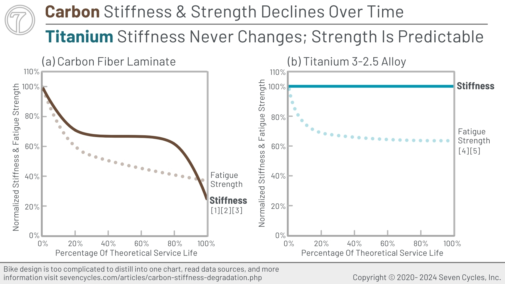
Figure 35-1 xxxxxxxxxx data sources.
Primary Cause of Stiffness Decline: Non-Structural Epoxy Resin
Individual carbon fibers require resin to hold them together and that typically takes the form of laminated sheets. Unfortunately, the epoxy resin offers almost no strength benefit as Figure 35-2 xxxxxxxxx illustrates. In fact, resin strength is so poor that it begins microcracking and delaminating during initial tensile or compressive loading.
Most epoxy resins used in bike frames has a fatigue limit of about 18 MPa (2.6 ksi). [6 xxxxxxx] That's less than 20% of aluminum 6061-T6 fatigue limit. [7 xxxxx]
Epoxy resin is at least 50% of the volume in CFRP. [8 xxxxx] That's a lot of non-structural surface area to delaminate and fail.
A reasonable question might be, "Aren't the carbon fibers doing all the work, not the resin? Unfortunately, no. That would be true if the carbon fibers were in 100% tension and in axis to the tensile load. However, in a bicycle frame, that's not what happens; the structure undergoes compression and tension cycles, generally in equal share. Even more problematic, bike stresses and loads are complex and have numerous axes. As soon as the fibers are off-axis to a tensile load, their fatigue strength is mitigated and almost nullified, as illustrated in Figure 35-2 xxxxxxxxx . So, we're back to relying on the resin to hold it all together. An impossible task.
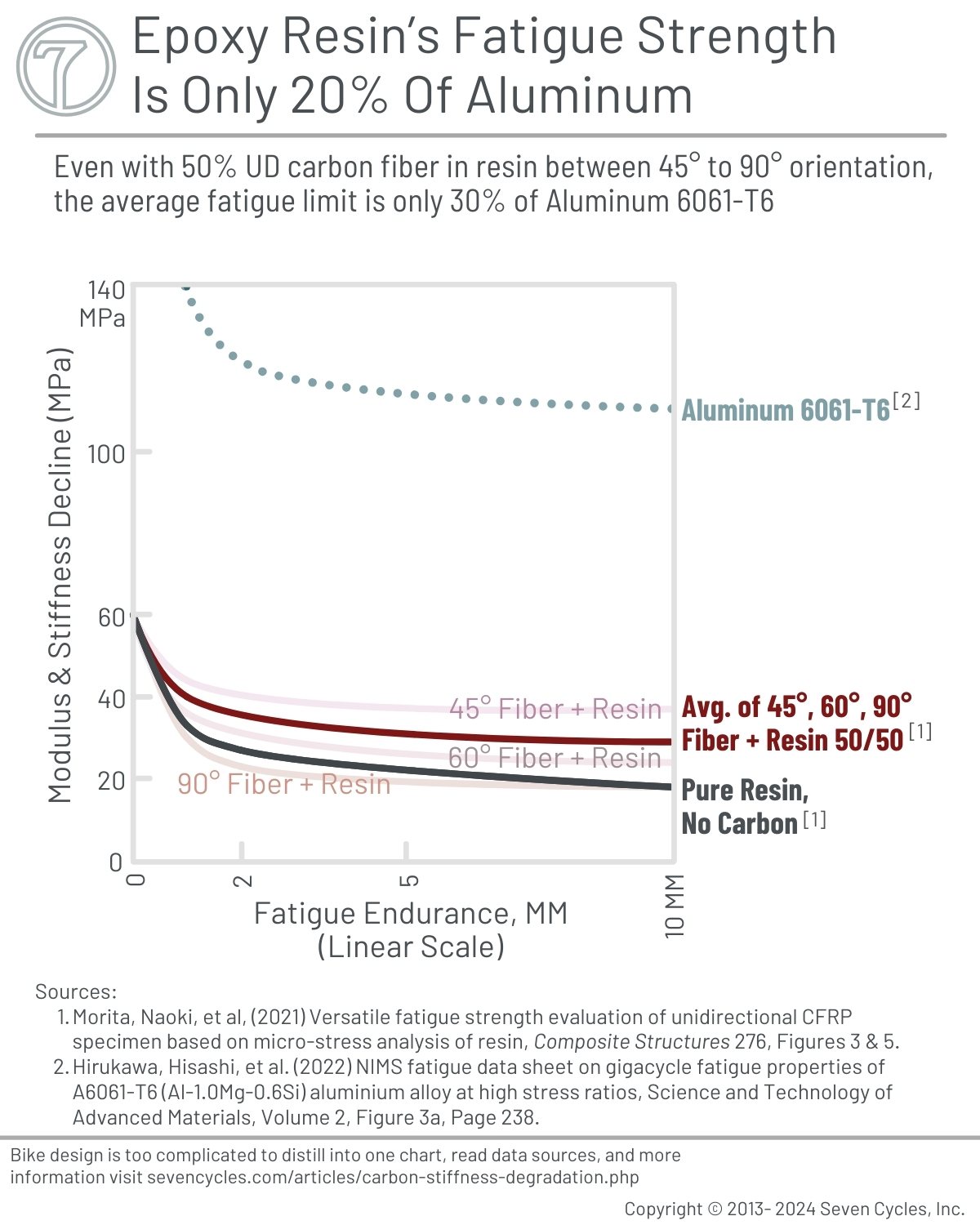
Figure 35-2 xxxxxxxxxx sources.
Defining Material Failure In Carbon Laminates
Carbon fiber laminates don't typically fail like metals. In cyclic fatigue situations (like bike riding) CFRP's lose stiffness over time. So, how is "failure" defined? What is the tipping point of failure in CFRPs?
CFRPs are typically considered to have failed when they lose between 1% and 20% of their stiffness. Conversely, metals are considered failed when they break.
Some people say that carbon fiber does not have a fatigue life. While true, it isn't a useful statement because bike frames and components are not made from 100% unidirectional carbon fibers undergoing exclusively tensile stress. Bike frames are built from carbon laminates that are 50% epoxy resin. These laminate fails progressively, first through microcracking of the resin that holds the carbon fibers together (Phase I in Figure 35-3). Microcracking leads to macrocracking (Phase II) which results in failure through accelerated stiffness loss or failure through breakage (Phase III).
Defining carbon failure in the 1% to 20%-plus range can be found in engineering literature:
From the ASTM-D6115-97 Standard Test Method for unidirectional continuous carbon fiber laminates:
"[...] number of cycles until the onset of delamination growth [...] the number of cycles until the compliance had increased by 1 % [third measure is] the number of cycles until the compliance has increased by 5 %. [...] the [...] 1% a value is [...] recommended for generating a conservative criterion for avoiding onset of fatigue delamination growth in durability and damage tolerance analyses of laminated composite structures." [9 xxxxxxx]
From NASA's research:
"A one to two percent decrease in the load at a constant maximum displacement indicated that the delamination had begun to grow." [10 xxxxxxx]
From the periodical Composite Structures:
"intermediate damage (approximately 10% stiffness loss) or extensively damaged (approximately 15% stiffness loss). The one specimen with complete delamination (approximately 20% stiffness loss) was considered to be completely failed and was not included in the following post-fatigue impact study." [11 xxxxxx]
"The [...] protocols generally resulted in approximately 15% stiffness loss and showed much more extensive delamination damage [...] regular intralaminar cracks were observed in the 90° and 45° plies for specimens from all loading conditions. These intralaminar cracks likely preceded the extensive delamination damage [...] and would be responsible for much of the initial loss in stiffness across all specimens." [12 xxxxxx]
"specimens [...] were mechanically fatigued with different load amplitudes leading to a loss in apparent stiffness of 10% to 15%. [...] In addition, transverse matrix cracks are observed in all fatigued specimens regardless of the amount of delamination." [13 xxxxxx]
"The laminates were fatigued at various stress ratios and exhibited delamination and intralaminar matrix cracking, resulting in a loss of axial stiffness in the range of 10% to 15%." [14 xxxxxx]
"The specimens [...] were loaded until a loss of stiffness of around 15% was observed after approximately 10,000 and 100,000 cycles, respectively." [15 xxxxxxx]
From the Journal of Composites Science:
"The control samples that were subjected to higher magnitude loading tended to catastrophically fail, [...] showing over 40% stiffness degradation for CF [carbon fiber]." [16 xxxxxxx]
"Phase I is characterised by an exponential drop in modulus." [17 xxxxx ]
From the Journal of Failure Analysis and Prevention article, A Common Model for Stiffness Degradation of Composites, Figure 8 [Figure 35-3 in this article] illustrates the end of fatigue endurance when a 4-5% reduction in stiffness is reached. [18 xxxxx ]
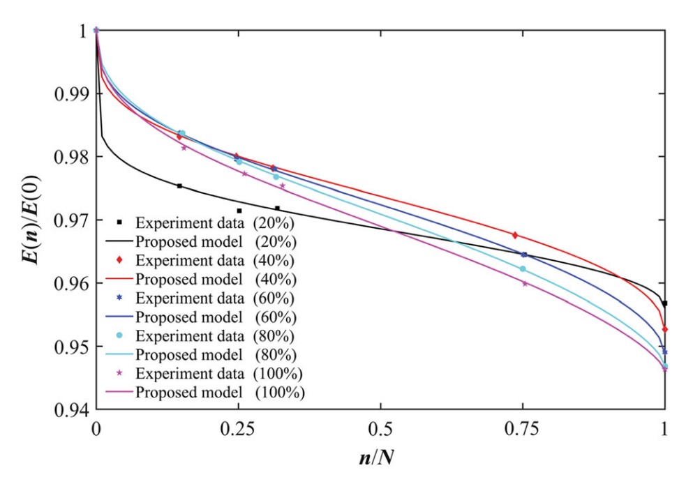
Figure 35-3 source: 18 xxxxx .
From the book Fatigue of Fiber-Reinforced Composites:
"for the design of structures containing rotating parts, like wind turbine or helicopter rotor blades, [...] blade functional failure is said to correspond to irreversible stiffness reduction of up to 10%." [19 xxxxx ]
"In the initial region [Phase I], and up to around 10% of fatigue life, the material exhibits a sudden stiffness reduction. In [stage II], the material's stiffness degrades at a constant and moderate rate. Finally, significant deterioration of the material can be observed close to the end of the fatigue life. A third region with a steeply descending slope simulates this phenomenon." [20 xxxxx]
"Such stiffness-controlled fatigue design curves [... have] been validated independently using experimental data from different material systems." [21 xxxxx]
"the derivation of S-N [fatigue strength] curves correspond to specific stiffness degradation." [22 xxxxxx]
Figure 35-4 illustrates xxxxxxxxxxxxxxxxxxxxxxxxxxxxxxxx
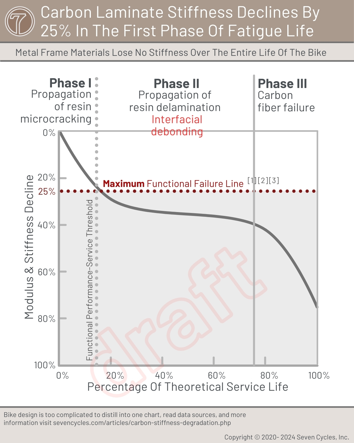
Figure 35-4 xxxxxxxxxx sources.
xxxxxxxxxxxxxxxxxxx Carbon's Stiffness & Modulus
xxxxxxxxxxxxxxxxx Carbon fiber's stiffness decline during use is substantial, noticeable, and has real-world effects on performance and rider happiness. Figure 21 and 22 xxxxxxxxxxxxxxx show this decline relative to titanium. The chart combines carbon fiber data from three third-party sources shown below. All show severe stiffness degradation within 10,000 cycles. For perspective, the average fitness cyclist pedals 10,000 revolutions in about 3 hours of riding. That's about 1,000,000 rotations per year. [23 xxxxxxxxxx ]
Figure 35-5 illustrates how carbon laminate stiffness decreases over time. All 16 data sources are third-party. All of the curves are similar and poor compared to the 3-2.5 titanium alloy with which Seven builds frames. All of the carbon curves fall off significantly within 10% of their fatigue lives. Titanium never loses measurable stiffness.
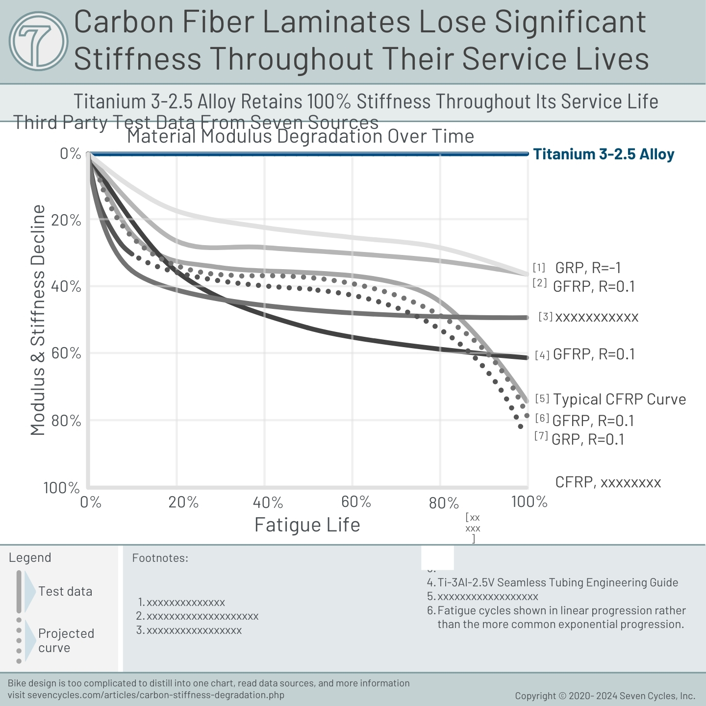
Figure 35-5 xxxxxxxxxxxxxxx sources.
Figure 35-6 illustrates the stiffness decline in stark relief. Within the first 20% of the CFRP's life, in most situations, the material would have failed most reasonable fatigue tests. The average stiffness loss is around 30%. Even the best case is around 15%. And, again, this is in just the first 20% of total fatigue life.
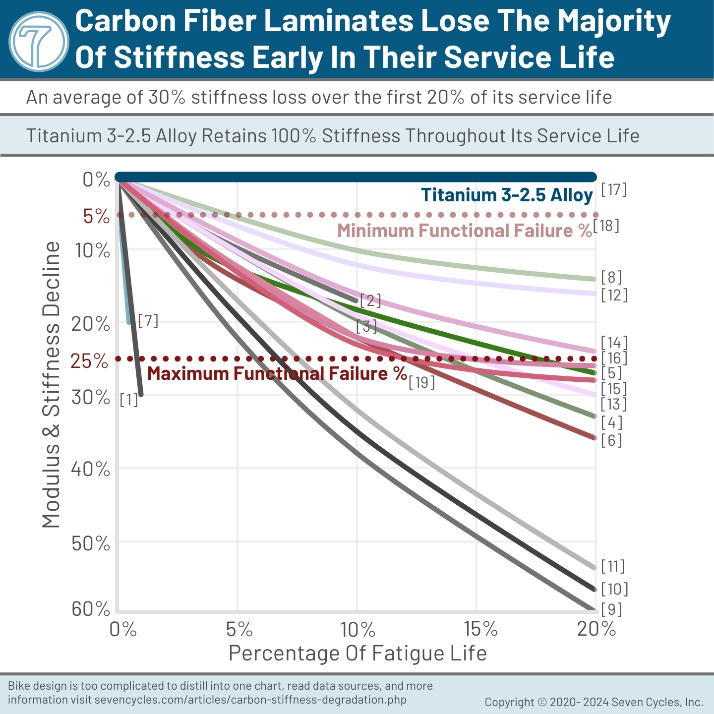
Figure 35-6 xxxxxxxxxxxxxxx sources.
How Many Cycles Does A Cyclist Cycle?
A cyclist who rides 10 hours a week will pedal more than 1,000,000 revolutions in a year. [23] A revolution is equivalent to a fully reversed tension-compression cycle in a classic R=-1 fatigue test. Of course, the average cyclist does not fatigue the frame on every single pedal stroke. Regardless, it is inescapable that the more pedal strokes, the more stiffness degradation occurs in a carbon frame. Titanium experiences no such stiffness loss.
Stiffness is typically measured by deflection under load or by the material's elastic modulus. Figures xxxxxxxxxxxxx 8, 9, and 10 show carbon fiber's elastic modulus decaying anywhere from 10% to 30% or more early in its fatigue cycle life, and it continues to decline throughout its life. In other words, the carbon bike that felt so good during its test ride will begin behaving differently as the miles pile on.
On the other hand, titanium exhibits no modulus degradation over its service life. The frame's stiffness characteristics on the first ride and the 10,000th ride are identical as shown in Figure 21 xxxxxxxxx.
Figure 8 shows material stiffness degradation of observed measurements and predicted degradation based on calculations. The figure also shows that the loss of stiffness is predictable and calculable when we have the correct data. The authors' calculated curve closely matches the test results.
In the test, at only 4,000 cycles (0.4 x 10⁴), the carbon laminate stiffness degrades by more than 17%. Stiffness loss exceeds 30% with only 35,000 cycles (3.5 x 10⁴). A small portion of the rider's time with the bike.[21 xxxxxxxxx]
Of course, the data in the accompanying figures are not equivalent to riding a carbon bike. Regardless, real-world tests repeatedly show stiffness decline in performance carbon frames. These data are simply a way to express the issue by using objective third-party testing.
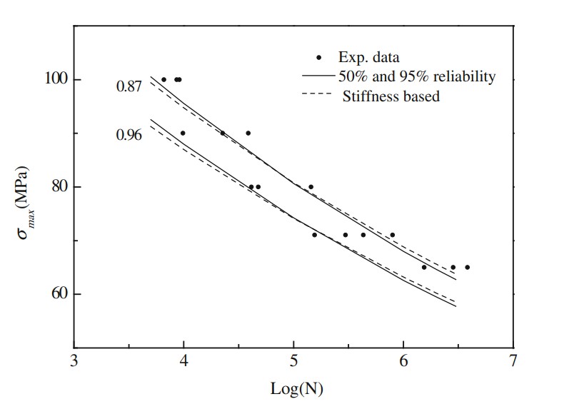
Figure 8:xxxxxxxxxxxxxxxxxxx .
Figure xxxxxxxx source: Vassilopoulos, Anastasios P., Keller, Thomas, 2011. Fatigue of Fiber-reinforce Composites, page 132, Figure 4.33.
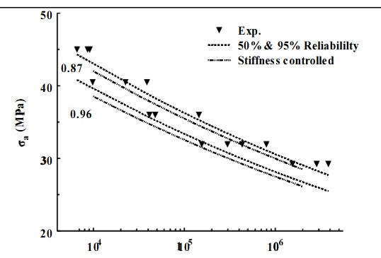
Figure 8:xxxxxxxxxxxxxxxxxxx .
Figure 8 xxxxxxxxxxxxxxxxxxx source: Stiffness Reduction of Composite Laminates under Combined Cyclic Stresses.
Solutions For Retaining Frame Stiffness For Years And Years
Make the Carbon Frame Stiffer
The only way to counteract carbon's modulus degradation is to prevent it from flexing. Unfortunately, that's not possible in a bike frame, but carbon framebuilders tend to make frames as stiff as possible to slow modulus degradation. This is at odds with the chase of ever-lighter frames that are, by definition, more flexible. Additionally, carbon requires stiffness in all planes to slow failure, including the vertical plane, meaning that full carbon frames built stiff enough to survive for a few years also produce unusual ride characteristics — like harshness over rough terrain, poor ground control, and a suboptimal ability to use body English.
Ride a Seven Titanium Frame (or any metal frame)
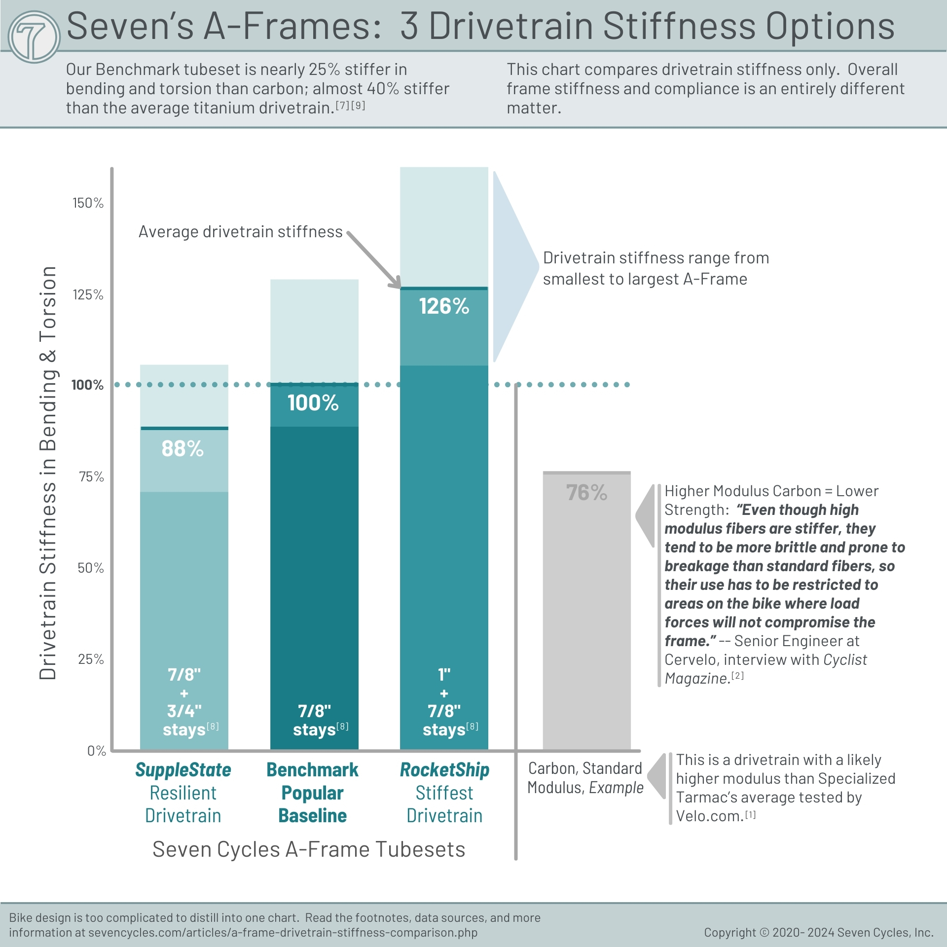
Fortunately, Seven's titanium designs address all these durability issues; its modulus never changes so the frame doesn't need to be overbuilt. Titanium has a high fatigue life, so you can allow some flex and flow vertically (while maintaining drivetrain stiffness) for ride quality improvement. Seven can even build extremely stiff frames when the request or need arises. Figure 35-xxxxxxxx xxxxxxxxxxx shows Seven's Rider-Ready drivetrain stiffness compared to carbon fiber.
Choose Seven's Carbon-Titanium Mix Frame
Seven's 622 and PRO chassis of carbon tubes with titanium lugs circumvents many of carbon's modulus degradation issues by employing three techniques that no high-end full carbon frame does.
- Titanium lugs: Seven's titanium lugs act as flexing members or joints, thereby reducing the carbon tube's point-load deflection.
- Stout carbon tubes: Our carbon tube walls are 2 to 3 times thicker than most contemporary performance carbon frame tube walls. This augmented layering substantially reduces localized tube flex and extends service life into the decades.
- Epoxy rather than resin: The epoxy Seven uses to bond carbon to titanium has about 200% higher elongation properties than typical carbon resin. Much of the bending stress is transferred from the carbon resin to the joint epoxy.
The success of Seven's process is evidenced by the tens of thousands of carbon tubes we've built frames with, Seven has yet to have a carbon tube fail from fatigue. The only carbon failures we've seen over the past 28 years have been from crashes, impacts, or poor treatment and maintenance.
Carbon Forks Versus Carbon Frames
"If carbon fiber has so many issues, why do Seven framesets usually come with carbon forks?"
If high quality carbon forks were as under-built and fragile as lightweight carbon frames, you'd probably never want ride them.
Read the data on how carbon frames are severely under built relative to carbon forks.
Footnotes for chapter 35 xxxxxxxxxxx
- ∧ Specialized Bikes owner's manual.
- ∧ Cannondale owner's manual.
- ∧ Cervelo owner's manual.
- ∧ Vassilopoulos, A. P., editor, (2015). Fatigue and Fracture of Adhesively-bonded Composite Joints - Behaviour, Simulation and Modelling, page 450.
- ∧ Vassilopoulos, A. P., editor, (2015). Fatigue and Fracture of Adhesively-bonded Composite Joints - Behaviour, Simulation and Modelling, page 450.
- ∧ Morita, Naoki, et al., (2021) Versatile fatigue strength evaluation of unidirectional CFRP specimen based on micro-stress analysis of resin, Composite Structures Volume 276. Figures 3 & 5.
- ∧ Hirukawa, Hisashi, et al., (2022) NIMS fatigue data sheet on gigacycle fatigue properties of A6061-T6 (Al-1.0Mg-0.6Si) aluminium alloy at high stress ratios, Science and Technology of Advanced Materials: Methods Volume 2, Pages 232-249, Figure 3. [R=-1]
- ∧ xxxxxxxxxxxxxxxxxxxxxxxx
- ∧ (2011) Standard Test Method for Mode I Fatigue Delamination Growth Onset of Unidirectional Fiber-Reinforced Polymer Matrix Composites, ASTM International D6115 - 97.
- ∧ Martin, R., et al., (1988) Characterization of Mode I and Mode II delamination growth and thresholds in graphite/peek composites, NASA National Aeronautics and Space Administration.
- ∧ Thomson, Daniel, et al., (2024) Influence of fatigue damage on the impact performance of toughened-interleave carbon fibre epoxy composite laminates, Composite Structures Volume 345, page 3.
- ∧ Thomson, Daniel, et al., (2024) Influence of fatigue damage on the impact performance of toughened-interleave carbon fibre epoxy composite laminates, Composite Structures Volume 345, page 3.
- ∧ Thomson, Daniel, et al., (2024) Influence of fatigue damage on the impact performance of toughened-interleave carbon fibre epoxy composite laminates, Composite Structures Volume 345, page 3.
- ∧ Thomson, Daniel, et al., (2024) Influence of fatigue damage on the impact performance of toughened-interleave carbon fibre epoxy composite laminates, Composite Structures Volume 345, page 3.
- ∧ Thomson, Daniel, et al., (2024) Influence of fatigue damage on the impact performance of toughened-interleave carbon fibre epoxy composite laminates, Composite Structures Volume 345, page 3.
- ∧ Blythe, Ashley, et al., (2022) Stiffness Degradation under Cyclic Loading Using Three-Point Bending of Hybridised Carbon/Glass Fibres with a Polyamide 6,6 Nanofibre Interlayer, Journal of Composites Science 6(9) 270.
- ∧ Blythe, Ashley, et al., (2022) Stiffness Degradation under Cyclic Loading Using Three-Point Bending of Hybridised Carbon/Glass Fibres with a Polyamide 6,6 Nanofibre Interlayer, Journal of Composites Science 6(9) 270.
- ∧ Feng, Zihao, et al. (2023) A Common Model for Stiffness Degradation of Composites at Material and Product Levels, Journal of Failure Analysis and Prevention, 23(4). Figure 8, page 1,556.
- ∧ Vassilopoulos, Anastasios P. et al. (2011) Fatigue of Fiber-Reinforced Composites, Page 130.
- ∧ Vassilopoulos, Anastasios P. et al. (2011) Fatigue of Fiber-Reinforced Composites, Page 129.
- ∧ Vassilopoulos, Anastasios P. et al. (2011) Fatigue of Fiber-Reinforced Composites, Page 130.
- ∧ Vassilopoulos, Anastasios P. et al. (2011) Fatigue of Fiber-Reinforced Composites, Page 130.
- ∧ Pedal strokes per year calculation: The assumptions are 90 cadence, 50% of the ride is pedal vs. coasting, and 10 hours per week. 2,700 revolutions per hour. 1,404,000 revolutions per year.
- xxxxxxxxxxxxxxxx: ∧ xxxxxxxxxxxxxxxxx xxxxxxxxxxxxxxxxxx
- ∧ Morita, Naoki, et al., (2021) Versatile fatigue strength evaluation of unidirectional CFRP specimen based on micro-stress analysis of resin, Composite Structures Volume 276.
- ∧ Vassilopoulos, Anastasios P. et al. (2011) Fatigue of Fiber-Reinforced Composites
- ∧ Blythe, Ashley, et al., (2022) Stiffness Degradation under Cyclic Loading Using Three-Point Bending of Hybridised Carbon/Glass Fibres with a Polyamide 6,6 Nanofibre Interlayer, Journal of Composites Science 6(9) 270.
Figure 35-1 xxxxxxxxxxxxxxxx sources:
- Vassilopoulos, Anastasios P. et al. (2011) Fatigue of Fiber-Reinforced Composites Page 129, Figure 4.31.
- Castro, Oscar, et al., (2019). Effect of matrix cracks on stiffness degradation of laminated composite beams. 22nd International Conference on Composites Materials. Page 1, Figure 1.
- Eliasson, Sara (2023) A Framework for Fatigue Analysis of Carbon Fiber Reinforced Polymer Structures KTH Royal Institute of Technology. Pages 15-18, Figure 2.9 & Figure 2.11.
- Forney, Clyde (1990). Ti-3Al-2.5V Seamless Tubing Engineering Guide, (Third Edition), page 35.
- Donachie, Matthew, Jr. (2000), Titanium A Technical Guide, (Second Edition), Pages 159-164.
Figure 35-2 xxxxxxxxxxxxxx sources:
- Morita, Naoki, et al., (2021) Versatile fatigue strength evaluation of unidirectional CFRP specimen based on micro-stress analysis of resin, Composite Structures Volume 276, Figures 3 & 5.
- Hirukawa, Hisashi, et al., (2022) NIMS fatigue data sheet on gigacycle fatigue properties of A6061-T6 (Al-1.0Mg-0.6Si) aluminium alloy at high stress ratios, Science and Technology of Advanced Materials: Methods Volume 2, Pages 232-249, Figure 3a. [R=-1]
Figure 35-3 xxxxxxxxxxxxxx sources:
- Vassilopoulos, Anastasios P. et al. (2011) Fatigue of Fiber-Reinforced Composites Page 129, Figure 4.31.
- Castro, Oscar, et al., (2019). Effect of matrix cracks on stiffness degradation of laminated composite beams. 22nd International Conference on Composites Materials. Page 1, Figure 1.
- Eliasson, Sara (2023) A Framework for Fatigue Analysis of Carbon Fiber Reinforced Polymer Structures KTH Royal Institute of Technology. Pages 15-18, Figure 2.9 & Figure 2.11.
Figure 35-4 and Figure 35-4 xxxxxxxxxxxxxxxx sources:
- Journal of Materials Research and Technology, Volume 21, November-December 2022: "The fatigue performances of carbon fiber reinforced polymer composites — A review." Figure 13
- Figure 37: Experimental Investigation of the Three-point Bending Fatigue Properties of Carbon Fiber Composite Laminates.
- Figure 39: Experimental Investigation of the Three-point Bending Fatigue Properties of Carbon Fiber Composite Laminates.
- Vassilopoulos, Anastasios P., Keller, Thomas, 2011. Fatigue of Fiber-reinforce Composites, page 129, Figure 4.31.
- [Figure 23]: Gerendt, Christian, et al., (2020) On the Progressive Fatigue Failure of Mechanical Composite Joints: Numerical Simulation and Experimental Validation, xxxxxxxx .
- [Figure 23]: Gerendt, Christian, et al., (2020) On the Progressive Fatigue Failure of Mechanical Composite Joints: Numerical Simulation and Experimental Validation, xxxxxxxxx.
- [Figure 10] Reference: Fatigue characterization of T300/924 polymer composites with voids under tension-tension and compression-compression cyclic loading.
- Figure 4: Figure 15 Stiffness Reduction of Composite Laminates under Combined Cyclic Stresses.
- Vassilopoulos, Anastasios P., Keller, Thomas, 2011. Fatigue of Fiber-reinforce Composites, page 132, Figure 4.33.
- Figure 15: Stiffness Reduction of Composite Laminates under Combined Cyclic Stresses.
- Vassilopoulos, Anastasios P., Keller, Thomas, 2011. Fatigue of Fiber-reinforce Composites, page 132, Figure 4.35.
- Liu, Zhe (2016) Evaluation of 3D failure modes in CFRP composite laminates, Nanyang Technological University, Singapore. Figure 4.5, 4.6, 4.7, pages 83-84.
- Feng, Zihao, et al. (2023) A Common Model for Stiffness Degradation of Composites at Material and Product Levels, Journal of Failure Analysis and Prevention, 23(4). Figure 6a, page 1,555.
- Feng, Zihao, et al. (2023) A Common Model for Stiffness Degradation of Composites at Material and Product Levels, Journal of Failure Analysis and Prevention, 23(4). Figure 6b, page 1,555.
- Michel, Silvain, et al. (2006) Fatigue strength of carbon fibre composites up to the gigacycle regime, International Journal of Fatigue, 28(3):261-270. Figure 6, page 265.
- Michel, Silvain, et al. (2006) Fatigue strength of carbon fibre composites up to the gigacycle regime, International Journal of Fatigue, 28(3):261-270. Figure 7, page 265.
- Forney, Clyde (1990). Ti-3Al-2.5V Seamless Tubing Engineering Guide, (Third Edition), page 35.
- Feng, Zihao, et al. (2023) A Common Model for Stiffness Degradation of Composites at Material and Product Levels, Journal of Failure Analysis and Prevention, 23(4). Figure 8, page 1,556. (At 95% stiffness the fatigue curve hits 100%.)
- Blythe, Ashley, et al., (2022) Stiffness Degradation under Cyclic Loading Using Three-Point Bending of Hybridised Carbon/Glass Fibres with a Polyamide 6,6 Nanofibre Interlayer, Journal of Composites Science 6(9) 270, page 21. "The control samples that were subjected to higher magnitude loading tended to catastrophically fail, [...] showing over 40% stiffness degradation for CF [carbon fiber]."
- Thomson, Daniel, et al., (2024) Influence of fatigue damage on the impact performance of toughened-interleave carbon fibre epoxy composite laminates, Composite Structures Volume 345, page 3. "complete delamination (approximately 20% stiffness loss) was considered to be completely failed and was not included in the following post-fatigue impact study." xxxxxxxxxxxxxxxxxxxxxxxxxxxxxx "referred to as either intermediate damage (approximately 10% stiffness loss) or extensively damaged (approximately 15% stiffness loss)." "The specimens [...] experienced approximately 10% stiffness loss, showed substantially lower amounts of delamination, with some of the cracks barely visible in the CT scans. [...] regular intralaminar cracks were observed in the 90 and 45 plies for specimens from all loading conditions." "approximately 15% stiffness loss [...] showed much more extensive delamination damage, reaching almost to the centre of the cross-section. Exceptionally, the delamination was seen to have propagated along the entire width of the specimen" "[...] a loss in apparent stiffness of 10% to 15%. Following the fatigue loading, high resolution computed tomography (CT) has been performed, revealing varying degrees of delamination [...] In addition, transverse matrix cracks are observed in all fatigued specimens regardless of the amount of delamination." "The laminates were fatigued at various stress ratios and exhibited delamination and intralaminar matrix cracking, resulting in a loss of axial stiffness in the range of 10% to 15%." "The specimens [...] were loaded until a loss of stiffness of around 15% was observed"
- Arimi, Ali, (2013) "Experimental Investigation Of Fatigue Behavior Of Carbon Fiber Composites Using Fully-Reversed Four-Point Bending Bending Test" Composite Materials and Joining Technologies for Composites Volume 7, Chapter 15. Pages 131-137.
- Belingardi, G, et al., (2006) "Bending fatigue behavior of glass/epoxy hybrid composites" Composites Science and Technology, Volume 66, issue 2, pages 222-232.
- Guo, Rui, et al., (2022) "The fatigue performances of carbon fiber reinforced polymer composites — A review" Journal of Materials Research and Technology, Volume 21, pages 4773-4789
- Forney, Clyde (1990). Ti-3Al-2.5V Seamless Tubing Engineering Guide, (Third Edition), page 35.
- UFS: Ultimate flexure stress.
- CFRP: Carbon fiber reinforced polymer.
- Fatigue cycles shown in linear progression rather than the more common exponential progression.